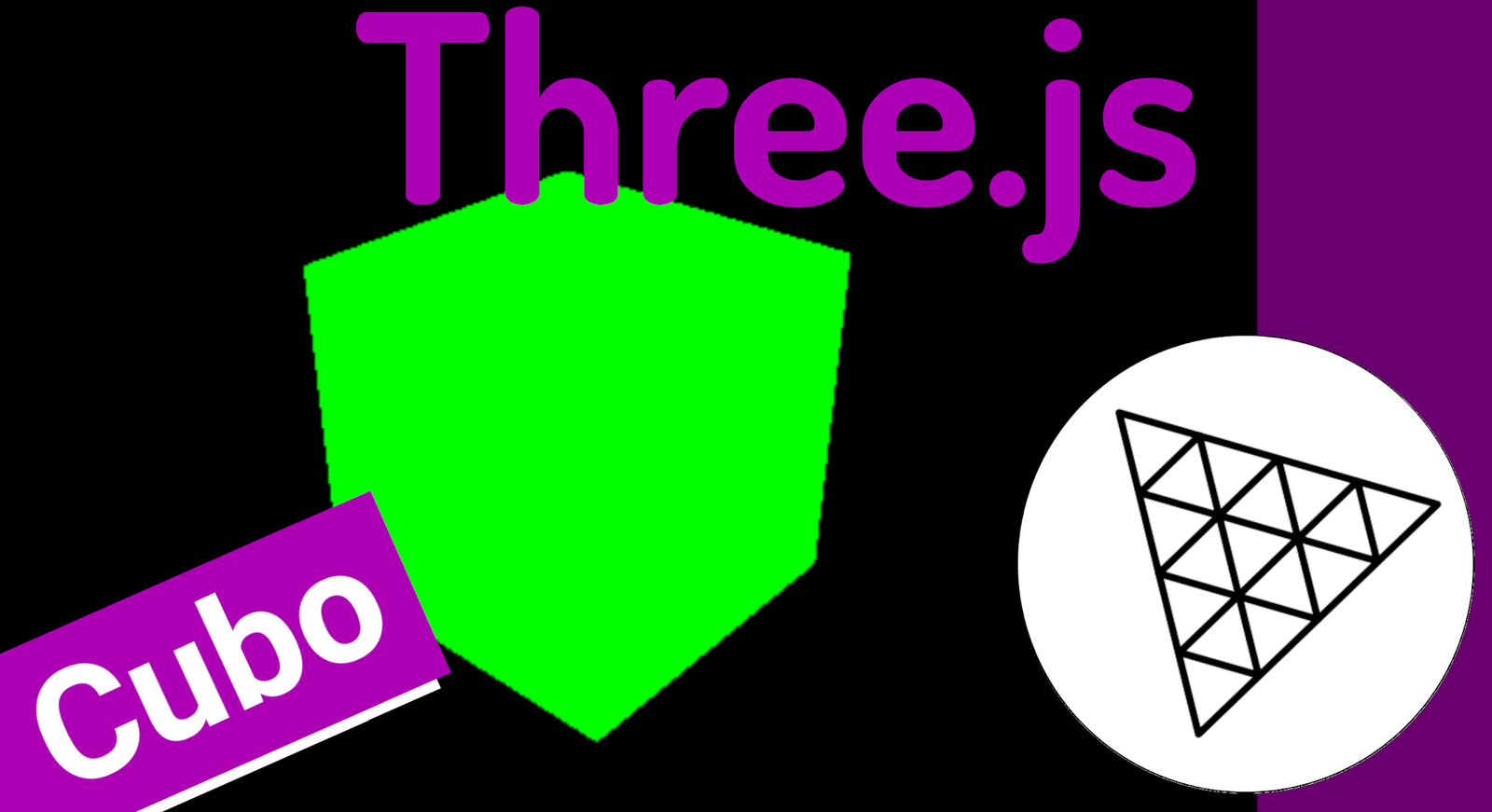
In this post, we are going to take the first steps with Three.js, creating a simple scene with several types of figures.
The cube is the favorite element that appears in software like Blender as the first geometric figure; for this, we need to complete 3 steps.
Fundamental Elements in Three.js
To render an object in Three.js we need 3 elements:
- The first element is the camera. The camera is the eye or the medium through which we can visualize our geometric figures. It can have various configurations depending on the needs, but usually a perspective camera is used, which allows visualization as if it were the human eye, meaning we can see depth.
- Another essential element is the scene. The scene is the space where we place our figures, in this example, a cube; therefore, you can think of it as the universe, which is nothing more than an empty space in which stars, planets... exist.
- Finally, we have our geometric figures, which is what we want to visualize; we can animate them, apply geometric operations such as translation, rotation, scaling, apply colors, materials, among others.
There is a fourth element which is the renderer, which is nothing more than the rendering engine that supports everything else.
Creating Our First Geometric Figure: A Cube
To render any 3D graphic in Three.js, we need three fundamental elements that will always appear together in any project:
- Scene: the universe or empty space where we will place all objects. Think of it as an infinite three-dimensional canvas.
- Camera: the eye or observer looking into that universe. Without a camera, we cannot see anything.
- Renderer: the engine that mathematically processes the scene and draws it into a
canvaselement within our HTML page.
The class code, with this we have the minimum example of creating a Three.js scene that consists of a scene, camera, render process, and a figure:
<!DOCTYPE html>
<html>
    <head>
        <meta charset="utf-8">
        <title>My first three.js app</title>
        <style>
            body { margin: 0; }
        </style>
    </head>
    <body>
        <script src="js/three.js"></script>
        <script>
            const scene = new THREE.Scene();
            const camera = new THREE.PerspectiveCamera( 80, window.innerWidth / window.innerHeight, 0.1, 1000 );
            const renderer = new THREE.WebGLRenderer();
            renderer.setSize( window.innerWidth, window.innerHeight );
            document.body.appendChild( renderer.domElement );
            const geometry = new THREE.BoxGeometry();
            const material = new THREE.MeshBasicMaterial( { color: 0x00ffff } );
            const cube = new THREE.Mesh( geometry, material );
            cube.position.y = 1
            scene.add( cube );
            camera.position.z = 2;
            renderer.render(scene, camera);
        </script>
    </body>
</html>
Explanation of the Previous Code
We create the render process with:
const renderer = new THREE.WebGLRenderer();
renderer.setSize( window.innerWidth, window.innerHeight );
In which we specify the screen size.
And we add it to the DOM:
document.body.appendChild( renderer.domElement );We also create the camera and the scene:
const scene = new THREE.Scene();
const camera = new THREE.PerspectiveCamera( 80, window.innerWidth / window.innerHeight, 0.1, 1000 );
We create a 3D figure; for that we have to create the geometry:
const geometry = new THREE.BoxGeometry();And the material, which can be several types, but the simplest is this one, where we can indicate a color:
const material = new THREE.MeshBasicMaterial( { color: 0x00ffff } );We position it where we want with:
cube.position.y = 1 We add the scene:
scene.add( cube );We reposition the camera:
camera.position.z = 2;And finally, we fire the render:
renderer.render(scene, camera);With this, we have a simple scene like the one shown on the cover of this publication.
Creating Wireframe or Mesh
We can easily activate the wireframe or mesh on our geometric figures using the `wireframe` option in the different meshes we create in Three.js.
Starting from a basic mesh for a cube, like the one we saw previously to create our first scene in Three.js:
const geometry = new THREE.BoxGeometry(4,4,4)
const material = new THREE.MeshBasicMaterial({ color: 0x00FF00})
We add the `wireframe` option; you can do this for most meshes supported by Three.js:
const geometry = new THREE.BoxGeometry(4,4,4)
const material = new THREE.MeshBasicMaterial({ color: 0x00FF00, wireframe: true })
And that's it; for the rest, we add it to the scene and we will have a figure like the one on the cover:
const cube = new THREE.Mesh( geometry, material )
scene.add( cube )
Creating a Sphere
In Three.js we have different figures that we can create, from rectangles or boxes as we saw in the first scene with Three.js, to spheres; to draw a sphere, we have the `SphereGeometry` function that obligatorily receives the radius, and the number of segments for the width and height:
THREE.SphereGeometry(20, 20, 20);For the rest, it follows the same structure as any other geometric figure that you want to establish; that is, passing the mesh and adding it to the scene:
var sphereGeometry = new THREE.SphereGeometry(20, 20, 20);
var sphereMaterial = new THREE.MeshBasicMaterial({
    color: 0x7777FF,
    wireframe: true
});
var sphere = new THREE.Mesh(sphereGeometry, sphereMaterial);
sphere.position.set(20, 4, 2);
scene.add(sphere);
Applying Rotations to Geometric Figures
In Three.js, the axes in its 3D environment for rotating 360 degrees require us to use radians, and with this we have to use PI; where a full PI is equivalent to 180 degrees; in this case, we want 180 degrees, that is, half a PI:
cube.rotation.x = Math.PI * .5In the previous example, we are applying it to a cube, which was the first geometric figure in Three.js that we created previously.
Creating a Plane
Like the sphere in Three.js that we generated previously, the important thing to note is that only the name of the geometric figure changes; in this case, the one for the plane is `PlaneGeometry`, which receives the width and length of the plane as parameters
const geometryPlane= new THREE.PlaneGeometry(14, 5)For the rest, you have to define the material and add it to the scene:
// plane
const geometryPlane= new THREE.PlaneGeometry(14, 5)
const materialPlane= new THREE.MeshBasicMaterial({ color: 0xFF0000, wireframe: false })
const plane= new THREE.Mesh( geometryPlane, materialPlane)
scene.add(plane)
Once the plane is added, you can vary its geometric transformations, for example:
//* POSITIONS
cube.position.x = -5
cube.rotation.x = Math.PI * .5
plane.rotation.x = Math.PI * -0.5
plane.position.set(0,-2,1)
Generating a Cartesian Axis
We are going to generate a helper figure, such as the 3D axis; with this, we will easily know where each of the 3D axes are; as such, it is not a figure with which we can make scenes:
const axesHelper = new THREE.AxesHelper( 10 );
scene.add( axesHelper );
Comparing Three.js with 3D tools like Blender
If you have ever used modeling software like Blender or engines like Unity, you will find that the architecture of Three.js is practically identical. In all these tools, there is:
- A space or universe (the scene) with X, Y, and Z axes where objects are placed.
- Geometric shapes (primitives) like cubes, spheres, or planes added to that space.
- A camera that determines the angle and perspective from which the scene is observed.
- A light source (which we will see later) to illuminate materials.
- A rendering process that converts 3D information into a 2D image.
The only fundamental difference is that in Blender we drag elements with the mouse, whereas in Three.js we do exactly the same thing but through JavaScript code. The underlying logic is the same.
Exercise: aligning sphere and cube of the same size
When we add multiple objects without specifying a position, they all appear at the origin (0, 0, 0), overlapping each other. To compose the scene correctly, we must manipulate the position property of each object.
An important difference between geometries must be noted: BoxGeometry defines the total size of the cube (width × height × depth), while SphereGeometry defines the radius, which is half the diameter. Therefore, for a cube with side 4 to occupy the same space as a sphere with radius 2 (diameter 4), both values must be calculated accordingly:
const geometry = new THREE.BoxGeometry(4, 4, 4)      // cube with side 4
const geometrySphera = new THREE.SphereGeometry(2, 20, 20)  // sphere with radius 2 = diameter 4
// move the cube to the left on the X axis
cube.position.x = -5
With this, both figures remain the same visual size and are separated on the X-axis. You can also use the position.set(x, y, z) method to define all three coordinates in a single instruction:
plane.position.set(0, -2, 1)Spatial Rotations
Any object in Three.js can be rotated through the rotation property, which works on the X, Y, and Z axes. The most important thing to remember is that rotations are not expressed in degrees but in radians.
To work comfortably with radians, we use the JavaScript Math.PI constant:
Math.PI * 2→ full 360° rotationMath.PI→ half turn of 180°Math.PI * 0.5→ quarter turn of 90°Math.PI * 0.25→ eighth turn of 45°
The sign of the value controls the direction: positive rotates in one direction, negative in the opposite.
cube.rotation.x = Math.PI * .5     // rotates the cube 90° on the X axis
plane.rotation.x = Math.PI * -0.5  // lays the plane down horizontally
Rotations can also correct visualization issues. If a cube and a sphere of the same size appear to have different dimensions when viewed from the front, a small rotation of the cube reveals its real depth and confirms that both objects are equal.
Generating a base plane
A plane is a flat rectangular surface created with PlaneGeometry. It accepts width and height as parameters, and optionally the number of segments in each dimension:
// plane
const geometryPlane = new THREE.PlaneGeometry(14, 5)
const materialPlane = new THREE.MeshBasicMaterial({ color: 0xFFFF00, wireframe: true })
const plane = new THREE.Mesh(geometryPlane, materialPlane)
scene.add(plane)
By default, the plane appears vertically, facing the camera, like a wall. To turn it into a floor or table, we must lay it down by rotating it 90° on the X-axis and then lowering its position in Y so it sits just below the other figures:
plane.rotation.x = Math.PI * -0.5   // lays the plane in a horizontal position
plane.position.set(0, -2, 1)        // moves it down and slightly forward
The result is a floor on which the cube and sphere visually rest, providing spatial context to the entire scene.
The AxesHelper: visualizing coordinate axes
When working in 3D space, it is easy to get confused with the orientation of the axes. Three.js includes the AxesHelper object specifically for this: it draws three colored lines starting from the origin and pointing to each axis:
- Red → X-axis (width, left-right)
- Green → Y-axis (height, up-down)
- Blue → Z-axis (depth, front-back)
const axes = new THREE.AxesHelper(5)
scene.add(axes)
axes.position.x = 3
The numerical parameter indicates the length of each line. The AxesHelper is a development aid object that should be removed before publishing the final project.
lookAt: pointing the camera at a target
When we raise or move the camera to get an interesting angle, it might stop pointing at the scene, and we might only see black. Manually calculating the exact rotation angles for the camera to look where we want is tedious and error-prone.
The lookAt() method solves this automatically: we pass it the coordinates of the point or object we want to observe, and Three.js calculates all the necessary rotation angles on its own:
camera.position.z = 9
camera.position.y = 7
camera.position.x = 8
camera.lookAt(cube.position)   // automatically points at the cube
We can also point at the center of the entire scene:
camera.lookAt(scene.position)Regardless of the camera's position, lookAt() guarantees it will always look at the specified target, greatly facilitating scene composition.
The complete source code
Below is the complete source code of everything we have built throughout this chapter. Each section is commented for easy reading:
<!DOCTYPE html>
<html lang="en">
<head>
  <meta charset="UTF-8">
  <meta name="viewport" content="width=device-width, initial-scale=1.0">
  <title>First steps with Three.js</title>
  <style>
    body { margin: 0; }
  </style>
</head>
<body>
  <script src="../js/three.js"></script>
  <script>
    // scene - universe
    const scene = new THREE.Scene()
    // camera or eye
    const camera = new THREE.PerspectiveCamera(80, window.innerWidth / window.innerHeight)
    // rendering
    const renderer = new THREE.WebGLRenderer()
    renderer.setSize(window.innerWidth, window.innerHeight)
    // add the render process to the document
    document.body.appendChild(renderer.domElement)
    // geometry, polygonal elements and other 3D shapes
    const geometry = new THREE.BoxGeometry(4, 4, 4)
    const material = new THREE.MeshBasicMaterial({ color: 0x00FF00, wireframe: true })
    // cube
    const cube = new THREE.Mesh(geometry, material)
    scene.add(cube)
    // sphere geometry and material
    const geometrySphera = new THREE.SphereGeometry(2, 20, 20)
    const materialSphera = new THREE.MeshBasicMaterial({ color: 0x00FFFF, wireframe: true })
    const sphera = new THREE.Mesh(geometrySphera, materialSphera)
    scene.add(sphera)
    // plane
    const geometryPlane = new THREE.PlaneGeometry(14, 5)
    const materialPlane = new THREE.MeshBasicMaterial({ color: 0xFFFF00, wireframe: true })
    const plane = new THREE.Mesh(geometryPlane, materialPlane)
    scene.add(plane)
    const axes = new THREE.AxesHelper(5)
    scene.add(axes)
    //*** POSITIONS
    cube.position.x = -5
    cube.rotation.x = Math.PI * .5
    plane.rotation.x = Math.PI * -0.5
    plane.position.set(0, -2, 1)
    axes.position.x = 3
    camera.position.z = 9
    camera.position.y = 7
    camera.position.x = 8
    camera.lookAt(cube.position)
    // render
    renderer.render(scene, camera)
  </script>
</body>
</html>
Chapter Summary
In this chapter, we established the foundations upon which any Three.js project is built:
- We configured the environment with Node.js and Vite for a modern workflow.
- We learned the essential triad: Scene, Camera, and Renderer.
- We created our first primitives:
BoxGeometry,SphereGeometry, andPlaneGeometry. - We activated the wireframe to understand the internal structure of the meshes.
- We manipulated
positionandrotation(in radians withMath.PI) to compose the scene. - We used
AxesHelperas a visual orientation tool during development. - We simplified camera orientation with the powerful
lookAt()method.
With these tools in hand, we are ready to move on to more complex scenes: animations, lighting, textures, and interactive controls that we will see in the coming chapters.
Source:
- https://github.com/libredesarrollo/curso-threejs-fundamentos-01/blob/main/base/esqueleto.html
- https://github.com/libredesarrollo/curso-threejs-fundamentos-01/blob/main/base/01_primeros_pasos.html
Garden Project
In this chapter, we will consolidate what we learned in the previous chapter by building a complete project from scratch: a small three-dimensional garden. The scene includes a green floor, a wooden fence that delimits the space, a tree composed of a trunk and foliage, and a house formed by a cylindrical base and a conical roof. Throughout the process, we will learn new geometries, advanced positioning techniques, and how to organize code into reusable functions.
Project Presentation
The final goal is a scene that at first glance seems simple —almost like a child's drawing— but contains several technical challenges:
- Composing objects by stacking various geometries (the house, the tree).
- Positioning each element correctly within 3D space.
- Discovering and using new geometries:
CylinderGeometryandConeGeometry. - Organizing code into functions to keep it clean and scalable.
The final result looks like this from above: a rectangular green plane surrounded by four brown bars forming a fence, a tree on the left, and a house on the right.
Preparing the HTML skeleton
The starting point is the same HTML skeleton from the previous chapter: a document with margin: 0 on the body, the Three.js library included, and a <script> block where we will work. We verify in the browser that a blank page appears without console errors before adding any objects.
The floor: PlaneGeometry as the garden ground
The first thing we build is the garden floor. We use a PlaneGeometry of 20 × 10 units with an intense green color. The plane initially appears standing up, like a wall, so we rotate it -90° on the X-axis to lay it flat and lower it slightly in Y to serve as the ground:
function floor(scene) {
    const planeGeometry = new THREE.PlaneGeometry(20, 10)
    const planeMaterial = new THREE.MeshBasicMaterial({
        color: 0x779922,
        wireframe: false
    })
    var plane = new THREE.Mesh(planeGeometry, planeMaterial)
    plane.rotation.x = -0.5 * Math.PI
    plane.position.y = -0.5
    scene.add(plane)
}
Note the use of wireframe: false: unlike the previous chapter, here we want a solid plane that simulates grass, not a wireframe. The value -0.5 * Math.PI is equivalent to -90° in radians.
The fence: reusing geometries and materials
The fence is made of four rectangular wooden bars surrounding the garden. Here we apply an important pattern: the same material can be assigned to several different meshes. We create the brown material only once and reuse it across the four bars:
function bar(scene) {
    const barMaterial = new THREE.MeshBasicMaterial({ color: 0x994422 })
    // left and right bars (Z axis, length 11)
    const geometryBarRightLeft = new THREE.BoxGeometry(1, 1, 11)
    const barRight = new THREE.Mesh(geometryBarRightLeft, barMaterial)
    barRight.position.x = 10
    scene.add(barRight)
    const barLeft = new THREE.Mesh(geometryBarRightLeft, barMaterial)
    barLeft.position.x = -10
    scene.add(barLeft)
    // top and bottom bars (X axis, length 19)
    const geometryBarUpBottom = new THREE.BoxGeometry(19, 1, 1)
    const barUp = new THREE.Mesh(geometryBarUpBottom, barMaterial)
    barUp.position.z = 5
    scene.add(barUp)
    const barBottom = new THREE.Mesh(geometryBarUpBottom, barMaterial)
    barBottom.position.z = -5
    scene.add(barBottom)
}
Observe the positioning logic: the garden is 20 units wide, so the origin is at the center. To place the right bar on the right edge, we move it +10 in X (half the width). The left one goes to -10. The front and back bars are placed at Z = ±5 (half of the 10 units of depth).
It is also possible to define two different geometries (one for the side bars and another for the front/back bars) because their dimensions are different: the side ones are long in Z and the front ones are long in X.
The tree: composition of two geometries
The tree demonstrates how to build complex objects by stacking simple primitives. It consists of:
- Trunk: a thin and tall
BoxGeometry(dark brown color). - Foliage: a low-segment
SphereGeometry(green color) placed on top of the trunk.
function tree(scene) {
    // TREE
    const trunkGeometry = new THREE.BoxGeometry(1, 8, 1)
    const trunkMaterial = new THREE.MeshBasicMaterial({ color: 0x110000 })
    const trunk = new THREE.Mesh(trunkGeometry, trunkMaterial)
    trunk.position.y = 3
    trunk.position.x = -3
    scene.add(trunk)
    const fodderGeometry = new THREE.SphereGeometry(4, 5, 6)
    const fodderMaterial = new THREE.MeshBasicMaterial({ color: 0x00AA00 })
    const fodder = new THREE.Mesh(fodderGeometry, fodderMaterial)
    fodder.position.y = 9
    fodder.position.x = -3
    scene.add(fodder)
    // END TREE
}
The trunk has a height of 8, so it grows 4 units up and 4 units down from its center. To make it start from the ground, we move it to y = 3. The foliage (radius 4) is placed at y = 9 to sit right on the tip of the trunk. Both share the same x = -3 position to align vertically.
Using few segments in the foliage sphere (5, 6) gives it a faceted and cartoonish look, consistent with the illustrative garden style.
The house: CylinderGeometry and ConeGeometry
The house introduces two new geometries. The base is a cylinder (CylinderGeometry) and the roof is a cone (ConeGeometry). The combination of both forms a stylized house.
CylinderGeometry receives: top radius, bottom radius, height, and number of segments. By using the same radius value for both top and bottom, we get a perfect cylinder:
function house(scene) {
    // House base
    const houseBaseGeometry = new THREE.CylinderGeometry(2, 2, 3)
    const houseBaseMaterial = new THREE.MeshBasicMaterial({ color: 0xFFEECC })
    const houseBase = new THREE.Mesh(houseBaseGeometry, houseBaseMaterial)
    houseBase.position.y = 1
    houseBase.position.x = 5
    scene.add(houseBase)
    // Cone-shaped roof
    const houseRoofGeometry = new THREE.ConeGeometry(2, 3, 15)
    const houseRoofMaterial = new THREE.MeshBasicMaterial({ color: 0x776600 })
    const houseRoof = new THREE.Mesh(houseRoofGeometry, houseRoofMaterial)
    houseRoof.position.y = 4
    houseRoof.position.x = 5
    scene.add(houseRoof)
    // END House
}
ConeGeometry receives: base radius, height, and number of segments. With 15 segments, the cone looks round enough to resemble a roof. If fewer segments were used (3 or 4), the result would be a pyramid.
Calculating heights is key for the base and roof to fit: the base has a height of 3 and its center is at y = 1, so its top edge is at y = 2.5. The roof is placed at y = 4 so its base starts at that same height without a visible gap.
An attempt was also made to use a BoxGeometry as the house base, but when trying to top it with the cone, a visual incompatibility arose: a square with a circular roof does not fit well. The cylinder, having the same circular section as the cone's base, produces a perfect join.
Refactoring: organizing code into functions
When all the code resides in a single flat block, scaling the application by adding more objects becomes chaotic. The solution is to encapsulate each element in its own function and create an init() function that initializes the base elements (scene, camera, renderer) and calls all the others, passing the scene as a parameter:
function init() {
    const scene = new THREE.Scene()
    const camera = new THREE.PerspectiveCamera(80, window.innerWidth / window.innerHeight)
    const renderer = new THREE.WebGLRenderer()
    renderer.setSize(window.innerWidth, window.innerHeight)
    document.body.appendChild(renderer.domElement)
    // calls to each garden element
    house(scene)
    bar(scene)
    tree(scene)
    floor(scene)
    camera.position.z = 20
    camera.position.y = 20
    camera.lookAt(scene.position)
    renderer.render(scene, camera)
}
init()
This pattern has clear advantages:
- No global variables: the scene is created inside
init()and passed as an argument to each function, avoiding access from the global scope. - Modularity: to add a new element, simply create a function
function myElement(scene)and call it frominit(). - Readability: each function has a single responsibility and its name describes what it builds.
Camera adjustment with lookAt
With several objects scattered in the scene, it is important to point the camera towards the center of the garden. Instead of manually calculating rotation angles, we use lookAt() pointing to the scene's position (the origin 0,0,0):
camera.position.z = 20
camera.position.y = 20
camera.lookAt(scene.position)
Positioning the camera at y = 20 and z = 20 gives a diagonal isometric angle that shows both the floor and the objects well. lookAt(scene.position) automatically rotates the camera to look towards the origin, regardless of where it is located.
Fine-tuning positions
Once all objects are assembled, it is common for some to float or intersect with the ground. Some adjustments made in this final phase:
- The floor is lowered to
y = -0.5instead of-1to eliminate dead space that remained between the floor and the base of the objects. - Floating objects are moved in Y until their base touches the plane.
- The fence bars are readjusted in Z to sit exactly on the edge of the plane without protruding or falling short.
To verify positioning, it is useful to temporarily change the camera position to observe the scene from different angles (from above with positive y, from below with negative y, from the side by adjusting only z). This helps detect objects that protrude or leave unwanted gaps.
The complete source code
<!DOCTYPE html>
<html lang="en">
<head>
  <meta charset="UTF-8">
  <meta name="viewport" content="width=device-width, initial-scale=1.0">
  <title>Garden Project</title>
  <style>
    body { margin: 0; }
  </style>
</head>
<body>
  <script src="../js/three.js"></script>
  <script>
    function init() {
        const scene = new THREE.Scene()
        const camera = new THREE.PerspectiveCamera(80, window.innerWidth / window.innerHeight)
        const renderer = new THREE.WebGLRenderer()
        renderer.setSize(window.innerWidth, window.innerHeight)
        document.body.appendChild(renderer.domElement)
        house(scene)
        bar(scene)
        tree(scene)
        floor(scene)
        camera.position.z = 20
        camera.position.y = 20
        camera.lookAt(scene.position)
        renderer.render(scene, camera)
    }
    function house(scene) {
        // House: cylindrical base
        const houseBaseGeometry = new THREE.CylinderGeometry(2, 2, 3)
        const houseBaseMaterial = new THREE.MeshBasicMaterial({ color: 0xFFEECC })
        const houseBase = new THREE.Mesh(houseBaseGeometry, houseBaseMaterial)
        houseBase.position.y = 1
        houseBase.position.x = 5
        scene.add(houseBase)
        // Cone-shaped roof
        const houseRoofGeometry = new THREE.ConeGeometry(2, 3, 15)
        const houseRoofMaterial = new THREE.MeshBasicMaterial({ color: 0x776600 })
        const houseRoof = new THREE.Mesh(houseRoofGeometry, houseRoofMaterial)
        houseRoof.position.y = 4
        houseRoof.position.x = 5
        scene.add(houseRoof)
    }
    function bar(scene) {
        const barMaterial = new THREE.MeshBasicMaterial({ color: 0x994422 })
        const geometryBarRightLeft = new THREE.BoxGeometry(1, 1, 11)
        const barRight = new THREE.Mesh(geometryBarRightLeft, barMaterial)
        barRight.position.x = 10
        scene.add(barRight)
        const barLeft = new THREE.Mesh(geometryBarRightLeft, barMaterial)
        barLeft.position.x = -10
        scene.add(barLeft)
        const geometryBarUpBottom = new THREE.BoxGeometry(19, 1, 1)
        const barUp = new THREE.Mesh(geometryBarUpBottom, barMaterial)
        barUp.position.z = 5
        scene.add(barUp)
        const barBottom = new THREE.Mesh(geometryBarUpBottom, barMaterial)
        barBottom.position.z = -5
        scene.add(barBottom)
    }
    function floor(scene) {
        const planeGeometry = new THREE.PlaneGeometry(20, 10)
        const planeMaterial = new THREE.MeshBasicMaterial({
            color: 0x779922,
            wireframe: false
        })
        var plane = new THREE.Mesh(planeGeometry, planeMaterial)
        plane.rotation.x = -0.5 * Math.PI
        plane.position.y = -0.5
        scene.add(plane)
    }
    function tree(scene) {
        // Trunk
        const trunkGeometry = new THREE.BoxGeometry(1, 8, 1)
        const trunkMaterial = new THREE.MeshBasicMaterial({ color: 0x110000 })
        const trunk = new THREE.Mesh(trunkGeometry, trunkMaterial)
        trunk.position.y = 3
        trunk.position.x = -3
        scene.add(trunk)
        // Foliage / leaves
        const fodderGeometry = new THREE.SphereGeometry(4, 5, 6)
        const fodderMaterial = new THREE.MeshBasicMaterial({ color: 0x00AA00 })
        const fodder = new THREE.Mesh(fodderGeometry, fodderMaterial)
        fodder.position.y = 9
        fodder.position.x = -3
        scene.add(fodder)
    }
    init()
  </script>
</body>
</html>
Chapter Summary
In this chapter, we applied all the foundations from the previous chapter to a realistic project:
- We built the floor with solid
PlaneGeometry(no wireframe) and rotated it using radians. - We learned CylinderGeometry: top radius, bottom radius, height, and segments.
- We learned ConeGeometry: base radius, height, and segments.
- We saw how to stack primitives to create complex objects (tree = trunk + sphere; house = cylinder + cone).
- We practiced reusing materials across multiple meshes.
- We refactored the code using functions with
sceneas a parameter, following theinit()pattern. - We adjusted the camera with
lookAt(scene.position)to frame the entire scene.
This pattern of separate functions per element is the foundation of the workflow we will use in more complex projects in the coming chapters.
Source: